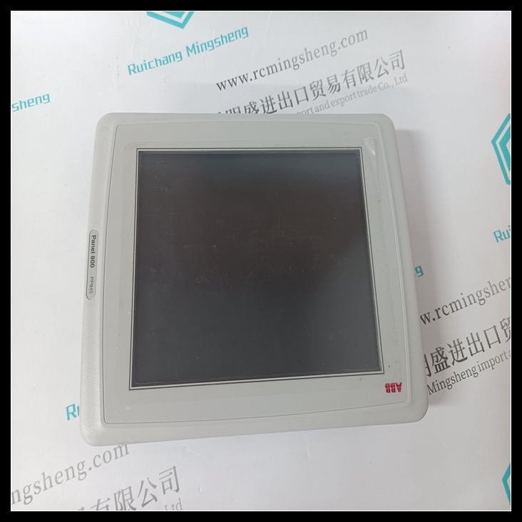
PP845触摸显示屏,PP845使用方法教程
冗余通信模块GFK-1446通信模块1998年2月,用力拉动电路板,将其从背板连接器上卸下。D沿卡导轨滑动板,然后将其从机架上卸下。状态指示模块顶部的五个绿色LED提供状态信息,如图3所示。PP845通电、配置电路板、RCM中没有诊断故障、与其他RCM建立通信(链路)时没有诊断故障以及链路上没有通信故障时,顶部LED(电路板正常)亮起。

其他LED(LOCAL READY、LOCAL ACTIVE、REMOTE READY和REMOTE ACTIVE)指示热备用CPU冗余系统中主设备和辅助设备的控制状态。有关每个指示灯的详细说明,请参阅《热备用CPU冗余用户指南》。单元选择按钮模块上的一个按钮,按下该按钮至少1秒后释放,如果两个单元都准备就绪,PP845触摸显示屏则允许您手动将控制从活动单元切换到备用单元。切换角色后,系统至少10秒钟内不允许再次切换。
Redundancy Communications
Module
GFK-1446
Communications Modules
February 1998
and pull the board firmly to remove it from the
backplane connector.
D
Slide the board along the card guide and remove it
from the rack.
Status Indications
The five green LEDs at the top of the module provide
status information as shown in figure 3. The top LED
(BOARD OK) is ON when power is applied, the board is
configured, there were no diagnostic failures in the RCM,
no diagnostic failures when establishing communications
(the link) with the other RCM, and no failures in
communications on the link.
The other LEDs (LOCAL READY, LOCAL ACTIVE,
REMOTE READY, and REMOTE ACTIVE) indicate the
control status of the Primary and Secondary units in a Hot
Standby CPU Redundancy system. For detailed
descriptions of each of these LEDs, refer to the Hot
Standby CPU Redundancy User’s Guide.
Unit Selection Pushbutton
A pushbutton on the module, which when depressed for at
least 1 second then released, allows you to manually
switch control from the active unit to the backup unit if
both units are ready. After switching roles, another switch
is not allowed by the system for at least 10 seconds.


