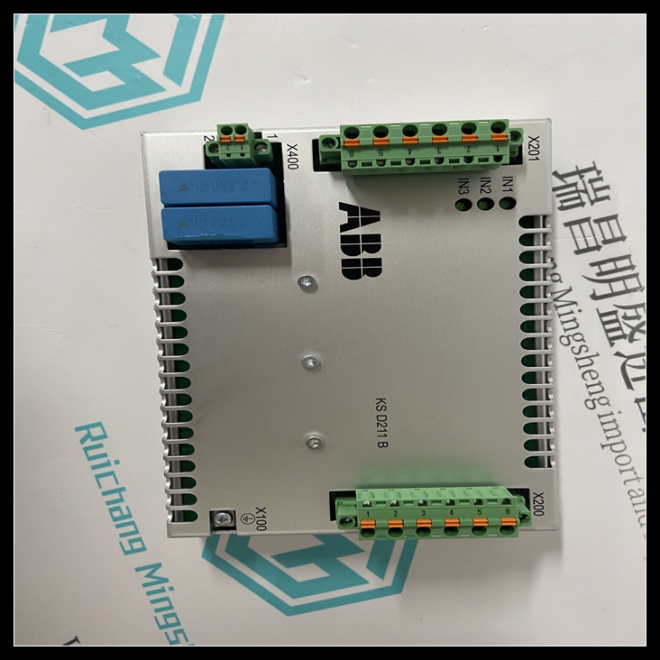
KSD211B控制卡,KSD211B使用方法教程功能D支持FIP冗余系统配置D每个系统所需的两个冗余通信模块(冗余机架中)D单插槽VME宽度模块D提供主PLC和辅助PLC之间共享I/O和同步消息的路径D高速并行总线扩展接口D板和系统状态的五个LED指示灯D手动切换的按钮开关主动到备份单元功能此冗余通信模块(RCM)KSD211B提供从主动到备份单元的同步消息路径,用于同步FIP单机架冗余系统中的两个CPU。它还提供了在两个单元之间传输共享I/O数据的路径。

FIP sindle rack冗余系统中各单元之间的物理连接总共可以有3英尺(0.9米)的互连电缆。FIP单机架冗余系统的CPU可以是IC697CFR782或IC697CFR28。模块在冗余机架中占用一个插槽,并有两个连接器,顶部连接器用于连接到其他机架部分中的总线变送器模块。底部连接器未使用。五个绿色LED提供RCM模块运行状况的状态指示,并监控热备用CPU冗余系统的控制状态。这些LED标记为BOARD OK、LOCAL READY、LOCAL ACTIVE、REMOTE READY和REMOTE ACTIVE。本地是指RCM所在的系统;远程是通过扩展总线连接的另一个系统。模块上的一个按钮允许您手动将控制从激活切换到备用单元(如果备用单元已准备就绪),从而允许在系统在线时维护先前激活的单元。必须使用MS DOSr或Windowsr编程软件配置功能将RCM配置到FIP冗余系统中。KSD211B控制卡
Features
D
Supports
FIP Redundant system configurations
D
Two Redundancy Communications
Modules required
per system (in redundancy rack)
D
Single slot VME width module
D
Provides path for shared I/O and synchronizing
message between Primary and Secondary PLCs
D
High Speed Parallel Bus Expansion Interface
D
Five LED indicators for board and system status
D
Pushbutton switch for manual switch from active to
backup unit
Functions
This
Redundancy
Communications
Module
(RCM)
provides
a
path for a synchronizing message from the active to the backup
unit which is used to synchronize the two CPUs in a FIP single
rack redundancy system. It also provides the
path for the
transfer of shared I/O data between the two units.
The physical
connection between
units in a
FIP
sindle
rack redundancy
system can have
up
to 3
feet
(0.9
meters) total of
interconnecting cable.
The CPUs for
FIP single rack
Redundancy systems
can be either IC697CFR782 or
IC697CFR28.
The module occupies a single slot in a redundant rack and
hastwo connectors, the top connector isfor attachment to the
Bus Transmitter Module in the other rack section. and the
bottom connector is unused.
Five green LEDs provide status indication of the health of the
RCM module and monitor the controlstatus ofthe Hot Standby
CPU Redundancy system. These LEDS are labeled BOARD
OK, LOCAL READY, LOCAL ACTIVE, REMOTE READY, and
REMOTE ACTIVE. Local refers to the system that the RCM
is in; remote is the other system connected through the
expansion bus
A pushbutton on the module allows you to manually switch
control from the active to the backup unit (if the backup unit
is ready) which allows maintenance of the previously active
unit while the system is on-line.
The RCM must be configured into the FIP redundancy
system using the MS-DOSr or Windowsr programming
software configuration function.


