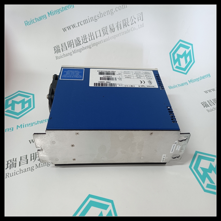
KOLLMORGEN PRD-B040SSIB-63控制卡,PRD-B040SSIB-63使用方法教程
通过将PLC1中同步程序中的逻辑长度增加到
PLC不同步,可测量最大逻辑量
该同步程序可用的解决方案时间。示例的测量值
系统如下表所示。通过增加PRD-B040SSIB-63控制
20ms逻辑的逻辑解算时间,直到程序变为
已同步。将20ms程序保持在该设置,另一个测量是
40ms同步程序采用相同的方式。此方法持续到
其余扫描集。下表将20ms同步程序分解为微循环。

FIP总线控制器第4章对这些部件进行了说明
用户手册。
当数据从FIP网络通过
FBC,并继续执行PLC应用程序。随着
数据离开PLC应用程序,通过FBC,并返回到FIP
网络示例2
KOLLMORGEN PRD-B040SSIB-63控制卡
在此示例中,将11个远程输入/输出机架添加到中所述的两个PLC网络
示例1。每个远程输入/输出机架具有相同的19个输入/输出模块;ALG222
(5) ,ALG392(6),MDL753(3),MDL655(5)。此配置在以下位置使用两个同步程序:
100ms和300ms的周期。
By increasing the length of the logic in a sync program in PLC1 to the point where the
PLC becomes out of sync, a measurement can be made of the maximum amount of logic
solution time available for that sync program. The measurements for the example
system are shown in the following table. The measurements were taken by increasing
the logic solution time of the 20ms logic to a point just before the program becomes
synchronized. Leaving the 20ms program at that setting, another measurement was
taken in the same fashion for the 40ms sync program. This method continued through
the remaining scan sets.The table below breaks down the 20ms sync program into the different components of
the microcycle. These components are explained in Chapter 4 of the FIP Bus Controller
User’s Manual.
The breakdown measures the data as it travels from the FIP network, passes through the
FBC, and continues to the PLC application program. The breakdown continues as the
data leaves the PLC application program, passes through the FBC, and returns to the FIP
network.Example 2
In this example, 11 remote I/O racks are added to the two-PLC network described in
example 1. Each remote I/O rack has an identical assortment of 19 I/O modules; ALG222
(5), ALG392 (6), MDL753 (3), MDL655 (5). This configuration uses two sync programs at
periods of 100ms and 300ms.


