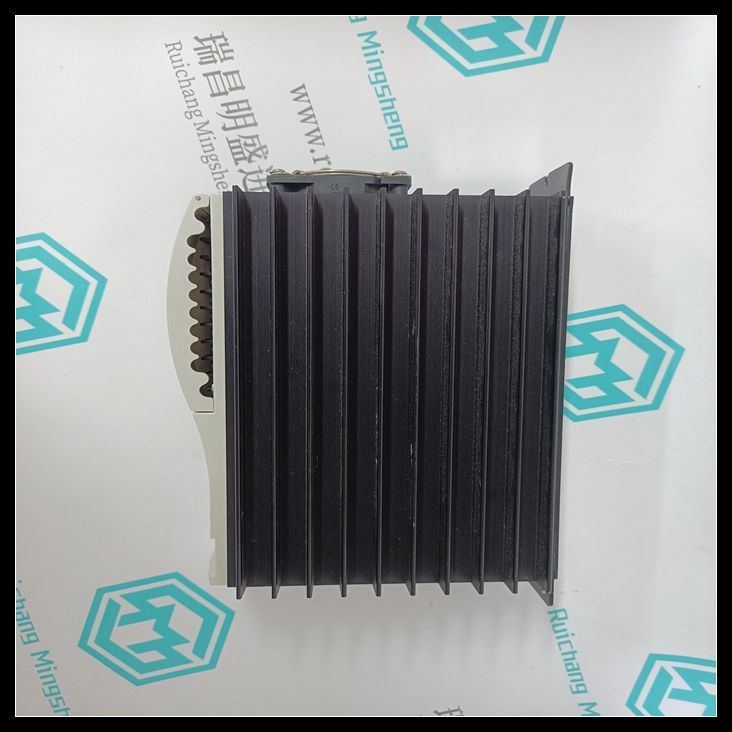
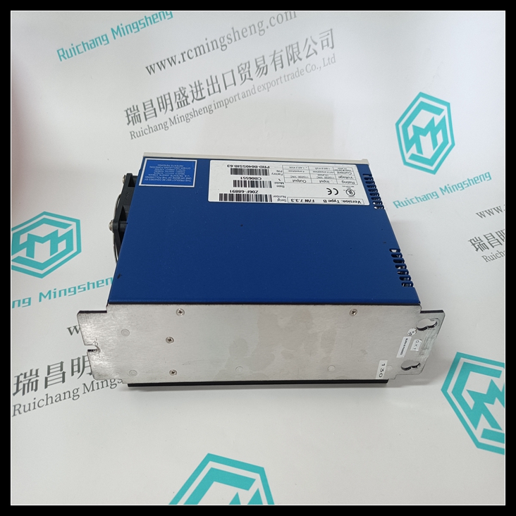
KOLLMORGEN CB06551机器人模块,CB06551说明书文档
总线控制器分别地它们也包含在CD-ROM文档库中。
此版本的FIP总线控制器的容量和性能CB06551
下面的信息为将来的回归测试提供了一个已知的基准。
它还可用于估计计划系统的性能。

该信息来自在完全运行的PLC和FIP上进行的实际测量
网络I/O数据仅由状态TVA组成。未配置验证程序TVA
用于网络上的exchange。要实现尽可能最佳的网络性能,请
建议消除验证程序TVA。KOLLMORGEN CB06551机器人模块
示例1
在此示例中,两个PLC(PLC1和PLC2)连接到FIP网络,如图所示
在下面PLC1和PLC2以20ms的周期配置4个同步扫描集,
40ms、80ms和160ms。PLC1中同步程序的逻辑增加一个值,并且
将其发送至PLC2中相应的同步程序。中每个同步程序的逻辑
PLC2只回显它接收到的数据。
Please retain this information with your Bus Controller User’s Manual (GFK-1038A). A
user manual is not shipped with the bus controller. User manuals can be ordered
separately. They are also included in the document library on CD-ROM.
Capacities and Performance of this Release of the FIP Bus Controller
The information that follows provides a known benchmark for future regression testing.
It also can be used to estimate the performance of a planned system.
This information is from actual measurements taken on a fully operational PLC and FIP
network. The I/O data consisted of state TVAs only. Validator TVAs were not configured
for exchange on the network. To achieve the best possible network performance, the
elimination of validator TVAs is recommended.
Example 1
In this example, two PLCs (PLC1 and PLC2) are connected to a FIP network as shown
below. PLC1 and PLC2 are configured with 4 synchronous scan sets at periods of 20ms,
40ms, 80ms, and 160ms. The logic of the sync programs in PLC1 increments a value and
sends it to the corresponding sync program in PLC2. The logic of each sync program in
PLC2 simply echoes the data it receives.


